BRIDGE6 MIDI Controller – User Manual (v2.1.7)
Quote
This device was created and designed to empower your creativity.
It is the result of many long nights and early mornings. It is born from the desire to bridge the gap between musician and instrument, and we want to say a huge thank you for your support. Our brand is built around a strong community and we hope you love your new MIDI controller as much as we do.
The PIRATE MIDI Team
BRIDGE6 Overview
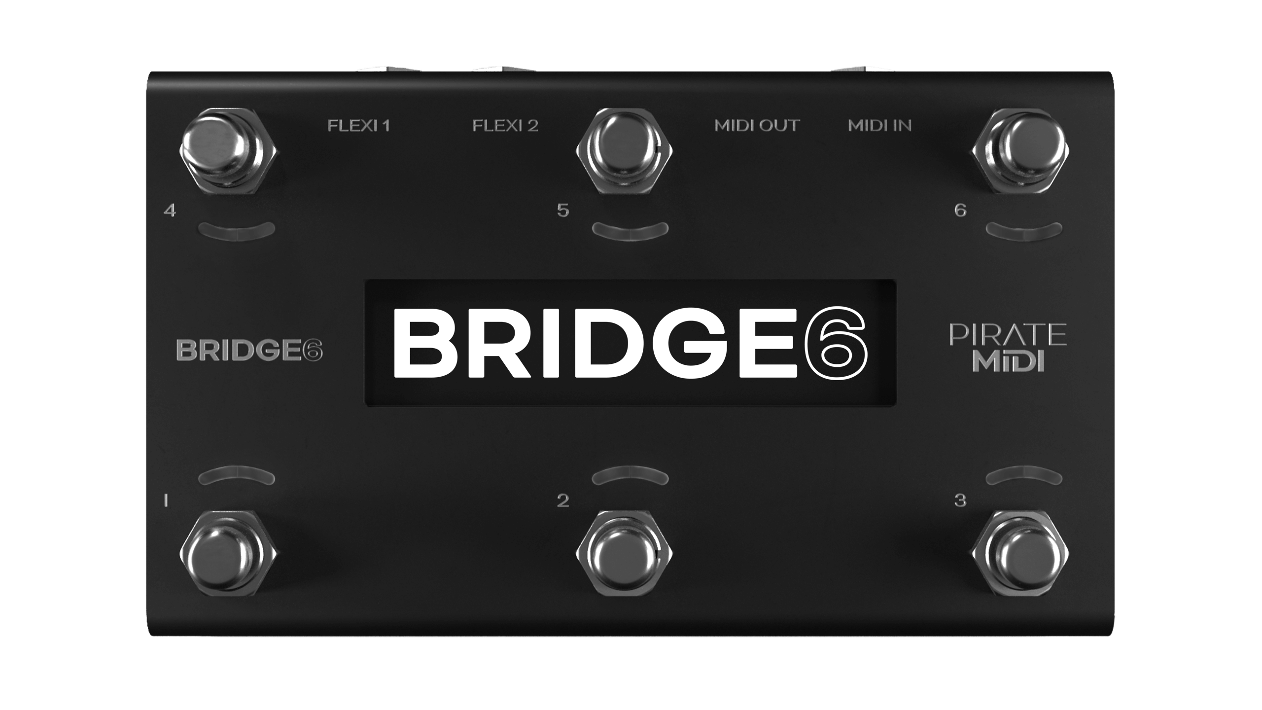
The BRIDGE6 is a 6-switch MIDI foot controller with RGB LEDs, an OLED screen, and a super tough aluminium enclosure. It’s made in New South Wales, Australia and was the result of a successful Kickstarter campaign in 2020. Now PIRATE MIDI builds and sells MIDI devices all over the world.
The BRIDGE6 can send stacks of MIDI messages through different footswitch press types (Press, Hold, Double-Press etc.) with 100 different banks of switches to scroll through. This means that the 600+ MIDI messages on each bank can be individually assigned across the whole device for a total of more than 60,000 unique messages and controls.
To help you connect to a wide variety of music gear, we’ve included two Flexiports of our own design. These ¼” (6.35 mm) TRS jacks can be set to whatever mode best suits your setup. From expression pedals to beat sync pulse to switch emulation, you can use this MIDI controller to control devices that don’t even have MIDI!
With all settings available to easily edit using the onboard display and menus as well as with the web editor, we hope you’ll agree that this is perfect for performing live or playing at home.
Technical Information
Links to Downloads
User manuals, firmware updates, and other downloads are available at:
It’s important that firmware updates are installed when they are available. Old firmware may not be supported by the web editor.
Firmware updates are released frequently and offer new features, bug fixes and other improvements.
Documentation is updated for each firmware update according to new features and changes.
Dimensions
- Metric: 160 × 94 × 63 mm
- Imperial: 6.3" × 3.7" × 2.5"
Display
- OLED 3.2"
Weight
- Metric: 550 g
- Imperial: 19.4 oz
Power Requirement
- 9 V DC or USB (200 mA)
Box Contents
- 1 × BRIDGE6 MIDI Foot Controller
- 1 × USB cable
- 4 × self-adhesive rubber feet
Hardware Layout
- Six soft-touch footswitches. No clicking. Work with multiple press types (double-press, hold, etc).
- Heavy-duty aluminium enclosure with black anodising. Scratch-resistant and no flex.
- Bright, crisp, and easy-to-read OLED graphical display. Menus, icons, and scribble strips are all a breeze on this display.
- Twelve RGB LEDs which you can assign to any colour you like for any function you like (flashing, solid, dim etc).
- Flexiports 1 and 2: multi-function ¼" (6.35 mm) TRS jacks which can be used in a number of different modes.
- 2.1 mm 9 V DC barrel jack, as standard on most effects pedals and power supplies.
- Dedicated ¼" (6.35 mm) TRS MIDI In conforming to the MIDI.org specification (Type A).
- Dedicated DIN5 MIDI Out conforming to the MIDI.org specification.
- USB Type-C (2 m Type-A-to-C cable included) for USB MIDI, using the web editor, and powering the device.
Quick Start
1. Bank Up / Bank Down

To go to the next bank, press switch 2 and switch 3 together.
To go to the previous bank, press switch 1 and switch 2 together.
These can be customised or turned off (see chapter 18, Bank Navigation).
2. Entering the Menu

To enter the onboard menu, hold switch 1 and switch 4 simultaneously.
All settings can be changed with onboard menus as well as the editor.
Hold switch 5 to exit the menu.
3. Don’t Miss the Rest!
Many menus and settings have a second or third page of settings. Always make sure you haven’t missed vital settings by scrolling to the right using switch 6 until you get back to the first position.
4. General Navigation
- Icons under or above each switch will show you what function they will serve.
- Generally switch 5 is a Back or Exit button, and switch 2 is an Enter or Select button.
- Switches 1 & 3 are up/down or value-changing controls.
- Switches 4 & 6 are sideways navigation to go to the next parameter.
Typical navigation:
- FS4 – Move Left
- FS5 – Exit / Back
- FS6 – Move Right
- FS1 – Down / Decrease
- FS2 – Save / Edit / Enter
- FS3 – Up / Increase
Check the MIDI Outputs
When you create a message, make sure you scroll across to the second/third screen to check that the message is being sent to the correct MIDI outputs (Flexiport 1, Flexiport 2, DIN5, or USB).
All outputs are on by default, but if you’re having trouble sending messages, you should check the outputs. Read more in chapter 8 (Message Stacks).
Set Flexiport Mode Before Using Flexiports
Before you plug something into a Flexiport, make sure you set the Flexiport mode in:
Menu → Global → Flexiports → Flexiport x → Mode
You won’t get the function you want unless you set the Flexiport mode. There is no mode set to the Flexiports by default – you must always set the mode.
Set Banking Program Change Outputs
By default, the BRIDGE6 sends Program Change (PC) MIDI messages out all four MIDI outputs when you change the bank (corresponding to the BRIDGE bank number).
If you want to turn some/all outputs off, or change the MIDI channel that the PCs are sent on, go to:
Menu → Global → MIDI → Banking PC Outputs
Switch Groups & Broadcast/Response Settings
When modifying switch group settings, the broadcast/response settings may seem overwhelming.
If you leave the defaults unedited, the switch will behave in a simple exclusive mode where only one switch will be on at a time. If you want to learn what these powerful settings are capable of, read more in chapter 13 (Switch Groups).
Check That Your BRIDGE6 Firmware Is Up to Date
Updates are released periodically adding new features and bug fixes. Go to:
!!! danger Technical documentation enclosed Coffee required.
1. Device Interface
Footswitches
Six silent footswitches are the main interface on the BRIDGE6. Rated for over 100,000 presses each, they can send different MIDI message stacks for different press types (Toggle On, Toggle Off, Press, Release, Double Press, Hold, Hold Release etc).
Each switch can send many different messages, and can be configured differently on every bank:
| Message Type | Max Messages |
|---|---|
| Toggle On | 16 |
| Toggle Off | 16 |
| Press | 8 |
| Release | 8 |
| Hold | 8 |
| Hold Release | 8 |
| Double Press | 8 |
| Secondary Toggle On | 8 |
| Secondary Toggle Off | 8 |
| Sequential Steps | 16 |
| Scrolling Messages | 16 |
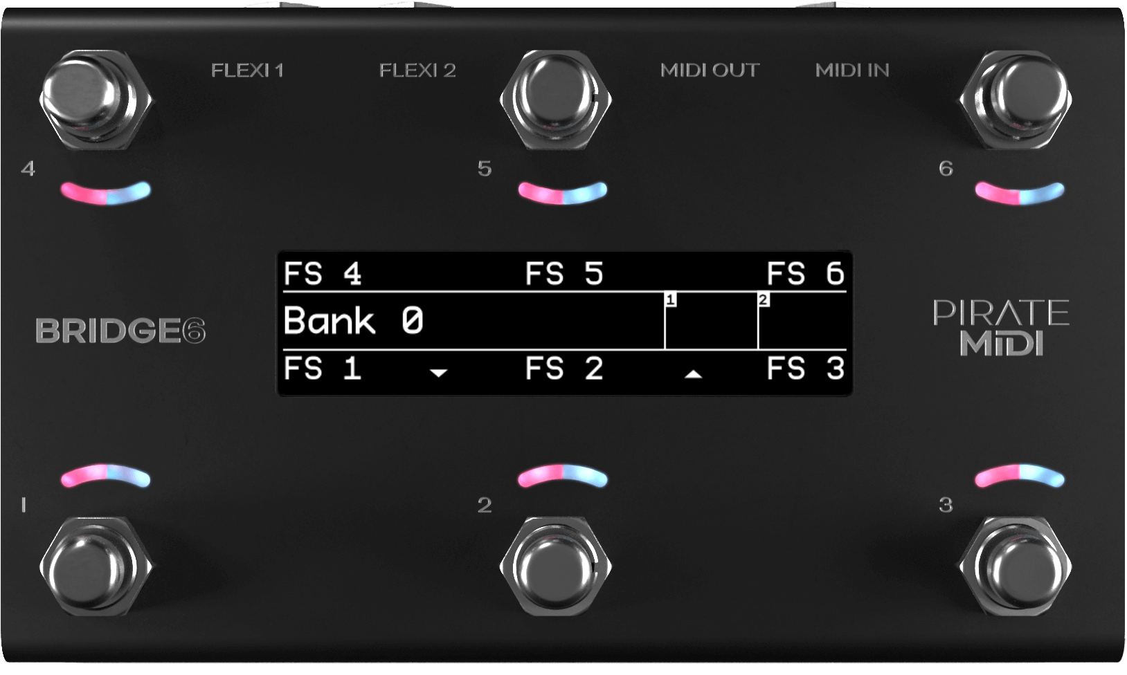
OLED Display
A large graphical display allows us to display symbols and icons to make the user interface easier to use.
The beauty of an OLED is the crisp, high-contrast display: easily readable from a distance with no need for a backlight.
By default, the OLED shows the bank name in the centre, and each switch label is set to FS x. Switch labels and bank names are editable through the onboard menus, the web editor, and our Device API.
RGB LEDs
Each switch is paired with a curved light pipe that houses two independent RGB LEDs. This means you can choose from millions of colours per switch and combine different LED states/colours to create your own custom interface.
Custom colours can be created:
- On the device
- In the web editor
- Via the API
- Via external MIDI commands
2. Power & Navigation
Powering Your BRIDGE6
You can power your BRIDGE6 with either:
- A USB cable, or
- A centre-negative 9V DC jack (2.1 mm) commonly used for guitar pedals.
Power Requirement
If you’re using a 9V DC power supply, make sure it can supply at least 200 mA.
Switching Power Sources
The BRIDGE6 uses smart power switching so you can have both USB and DC plugged in at once. If you need to remove one or the other, the unit will seamlessly switch power sources without shutting down or restarting.
Basic Navigation – Bank Up & Bank Down
As indicated by the arrows at the bottom of the OLED screen:
- Pressing switches 2 & 3 at the same time will advance to the next bank (Bank Up).
- Pressing switches 1 & 2 at the same time will go to the previous bank (Bank Down).
Holding down the bank change triggers will result in an automatic scroll through the banks. Bank scrolling accelerates the longer you hold the switches.
There are 100 banks (1–100).
- Banking up from bank 100 will return you to bank 1.
- Banking down from bank 1 will send you to bank 100.
Banks can be counted from 0–99 or 1–100 using the global interface settings.
Opening the Menu
To enter the menu, press and hold switches 1 & 4 simultaneously (as pictured above). You will know you’ve entered the menu when the screen layout changes.
- Press switch 1 or switch 3 to navigate the menu vertically (note the arrows on screen).
- Press switch 4 or switch 6 to change bank or navigate horizontally in the menu (note the arrows on the screen).
- Press switch 2 to select or set (like an Enter or Return key on a computer).
- Press switch 5 to go back to the previous menu screen or exit the menu.
- Hold switch 5 on any menu screen to completely exit the menu.
Second-Screen Settings
When editing parameters like MIDI message details, LFO settings etc., there may be a second (or third) screen of settings.
To access these pages, use the left and right arrows on switches 4 & 6 to navigate horizontally across the screen.
These pages are circular – navigating in one direction will always bring you back to the place you started.
Ready to Rock
That’s the end of the basic navigation instructions. After this you should be able to figure out how to navigate all the menus and settings.
You can watch the tutorial videos on our YouTube channel for a visual explanation.
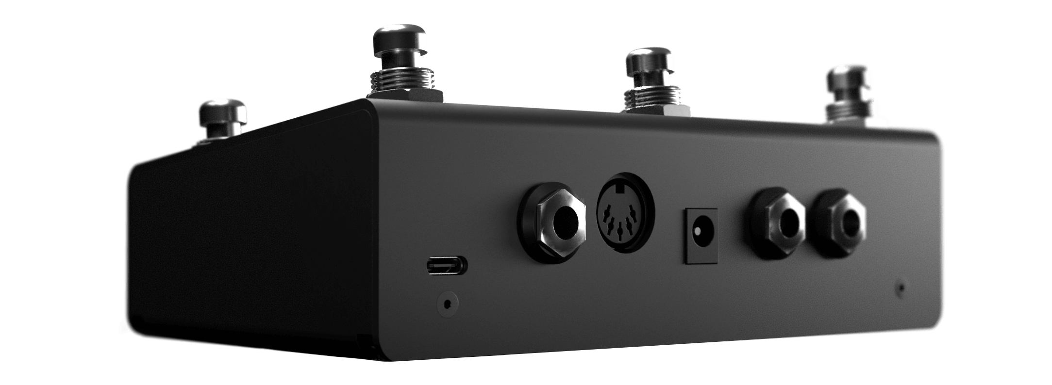
3. Overview of Connectors
From left to right:
USB (Type-C)
The BRIDGE6 can be powered by USB and is also a class-compliant USB MIDI device. This means it will be recognised as a MIDI device without any drivers.
Use it with:
- Your DAW
- Plugins
- Music apps
TRS MIDI In
A ¼" (6.35 mm) TRS jack designated as a dedicated MIDI input. This input conforms to the MIDI Specification (Type A).
DIN5 MIDI Out
A DIN5 jack designated as a dedicated MIDI output. This MIDI output:
- Conforms to the MIDI Specification
- Can power CME WIDI products
9V DC (centre-negative)
A 2.1 mm centre-negative barrel jack (standard for most guitar pedal power supplies). Requires 200 mA.
TRS Flexiports 1 & 2
¼" (6.35 mm) TRS jacks with 12 modes:
- MIDI Out – Type A
- MIDI Out – Type B
- MIDI Out – Tip Active
- MIDI Out – Ring Active
- Device Link
- Exp-Doubler In
- Expression In
- Aux Switch In
- Switch Out
- MS Relay Out
- Tap Tempo Out
- Pulse Clock Out
The extreme flexibility of the BRIDGE6 is due partly to the two Flexiports we’ve included. The Flexiport is a multi-function TRS port that we’ve designed (and named) to give you a truly flexible experience with our devices.
Flexiports will be included in most PIRATE MIDI devices and will offer the same functionality across all devices. So if you see the name Flexiport, you know what it does.
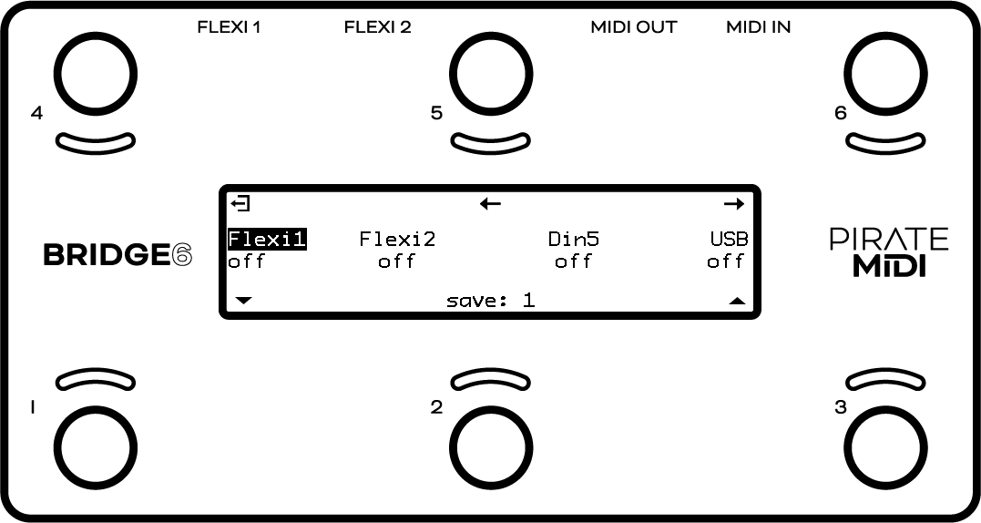
4. Flexiports
Flexiport Modes Summary
Each Flexiport on the BRIDGE6 is a 6.35 mm (¼") TRS jack. They have 12 modes that are assignable in the menu under:
Menu → Global → Flexiports → Flexiport x → Mode
The modes are:
| Flexiport Mode | Description |
|---|---|
| MIDI Out – Type A | Can power CME WIDI devices. Type A is the MIDI TRS standard |
| MIDI Out – Type B | Used by brands such as Arturia, Novation, and others |
| MIDI Out – Tip Active | Used by Empress, Alexander Pedals, Meris, Bondi Effects and more |
| MIDI Out – Ring Active | Used by Chase Bliss Audio. |
| Device Link | Connect multiple PIRATE MIDI devices together |
| Exp-Doubler In | Enables two expression pedal inputs per Flexiport with the PIRATE MIDI Exp-Doubler device |
| Exp In | Single TRS expression pedal input |
| Aux Switch In | 1, 2, or 3 switch TRS aux switches supported – add more footswitches to your controller |
| Switch Out | Send TRS switch emulation to non-MIDI devices |
| MS Relay | Send TRS commands to your Morningstar Omniport Relay Interface |
| Tap Tempo Out | MIDI Clock as switch output |
| Pulse Clock Out | Send MIDI clock as a square wave to sync non-MIDI devices |
Flexiport Warning
Flexiports offer many operating modes. Not all of these modes are compatible with external devices.
In particular, the Switch Out mode allows a Flexiport to emulate a TRS switch output. This is designed to control devices that have an auxiliary switch input or tap tempo footswitch jack, where the device that is connected does not have more than 3.3 V on the jack the Flexiport will connect to.
This can be tested using a TRS patch cable and a multimeter.
Many devices use larger operating voltage and/or currents than the 3.3 V that a Flexiport can handle. Please contact us to see if your device may be compatible with this mode if you are unsure.
A Flexiport can also be damaged when using an incorrect mode with an external device attached. Make sure that you have enabled the correct Flexiport mode before connecting an external device.
Ignoring these warnings may void your warranty
Please make sure to contact us if you’re unsure: Email: support@piratemidi.com
MIDI Out (Flexiports)
When set to “MIDI Out” mode, the Flexiport is a dedicated MIDI TRS output. There are four MIDI Out modes:
- Type A
- Type B
- Tip Active
- Ring Active
Choose the MIDI Out mode in the Global Settings menu:
Menu → Global → Flexiports → Flexiport x → Mode → MIDI Out (type x)
TRS A is the standard MIDI specification for TRS MIDI. It uses the Tip to send MIDI. However, because MIDI over TRS was introduced before the specification was decided, some brands send on the Ring (TRS B).
There are also brands who do not adhere to the specification and only use two pins instead of three to send MIDI data. Brands such as Empress, Meris, Bondi Effects, Alexander Pedals, and Chase Bliss Audio use either Tip Active or Ring Active modes.
If you are unsure which pedals or devices use which mode, a quick web search will usually answer your question. If you’re having trouble finding out, feel free to ask in our Facebook group (which will get the fastest response), or email support@piratemidi.com
Once the Flexiport is in MIDI Out mode, any messages that have their MIDI output set to that Flexiport will be transmitted out that Flexiport when the messages are triggered.
Expression Pedal In
When set to “Exp In” mode, the Flexiport receives analogue expression pedal input for conversion to MIDI.
Set the Flexiport to Exp In mode in the Global Settings menu:
Menu → Global → Flexiports → Flexiport x → Mode → Exp In
You will now see the expression pedal graph in the Extended UI for the Flexiport you have put in Exp In mode.
Note
This is designed to work with TRS expression pedals only. TS expression pedals will not work.
Expression Pedal Calibration
Expression pedals will sometimes not register their full range on different devices they connect to. Calibrating your expression pedal will make sure that:
- Toe-down = MIDI value 127 (maximum)
- Heel-down = MIDI value 0 (minimum)
Calibrate your expression pedal in the menu:
Menu → Global → Global Exp Pedals → Exp xx → Calibrate
Follow the on-screen instructions to calibrate the pedal. The device will instruct you to put the pedal at the full toe-down position for 5 seconds, and then the heel-down position for 5 seconds.
Exp-Doubler In
When set to “Exp-Doubler In” mode, usage is the same as Exp In (including calibration), but this mode can only be used with the PIRATE MIDI Exp-Doubler.
Set it in the menu:
Menu → Global → Flexiports → Flexiport x → Mode → Exp-Doubler In
The Standard UI will now show two expression pedal graphs for the Flexiport you have set to Exp-Doubler mode.
An expression pedal usually works with three contacts: Tip, Ring, and Sleeve.
- The Ring supplies power
- The Sleeve is connected to ground
- The Tip transmits the position of the pedal
The Exp-Doubler supplies power to the Ring of your expression pedals, which leaves an extra slot on the Flexiport for receiving the pedal position. Across two Flexiports this means up to 4 expression pedals can be used – two per Flexiport.
Expression pedals are therefore labelled as 1A and 1B, 2A and 2B.
Tap Tempo Output
When set to “Tap Tempo Out” mode, the Flexiport is a dedicated analogue TRS output which sends switch impulses synced to the chosen MIDI clock (Clock A or Clock B).
It can be put in Clock A or Clock B mode in the Global Settings menu:
Menu → Global → Flexiports → Flexiport x → Mode → Tap Tempo Out → MIDI Clock x
Now, connect a TRS cable from the Flexiport to the device you wish to send the tap tempo to, and you should see the tap tempo changing on your non-MIDI device.
Example devices that accept Tap Tempo Out include:
- MXR Carbon Copy Deluxe
- BOSS DD-20 Giga Delay
Aux Switch In
When set to “Aux Switch” mode, the Flexiport receives auxiliary switch input for extra footswitch controls.
Set the Flexiport mode in the Global Settings menu:
Menu → Global → Flexiports → Flexiport x → Mode → Aux Switch
Single, double, or triple auxiliary switches will work in this mode. Plug your aux switch into your Flexiport and then assign it a function or MIDI command:
- For global aux messages:
Menu → Global → Aux Switches → Aux Switch x - For bank-level aux messages:
Menu → Aux Switches → Aux Switch x
Using these menus, you can assign messages for up to three auxiliary switches (Tip, Ring, Tip+Ring). The available message types are:
- Press
- Hold
- Toggle On
- Toggle Off
These messages are available to configure individually for every bank, but also globally. This means that each switch can send two messages at once for press, toggles, and holds.
All message types, including Smart Messages, can be assigned to Aux Switches.
When in Aux Switch mode, the Standard UI will show dynamic switch icons. The centre of the circle will fill when a press is registered, and the circle will be filled completely when a switch hold is registered.
Switch Out
When set to “Switch Out” mode, the Flexiport acts like an analogue switch. This can be used to control functions on non-MIDI pedals that have a switch input (for example, tap tempo inputs or other footswitch functions).
Set the Flexiport to Switch Out mode in the Global Settings menu:
Menu → Global → Flexiports → Flexiport x → Mode → Switch Out
Examples of devices with compatible footswitch inputs include:
- BOSS MS-3
- MXR Carbon Copy Deluxe
- Line 6 HX Stomp
- BOSS DD-20 Giga Delay
When in Switch Out mode, the Standard UI will show a dynamic Tip & Ring icon, which fills the Tip, Ring, or Tip+Ring when those commands are triggered.
Assigning “Switch Out” Actions to a Footswitch
Once you have set the Flexiport mode, you can set any message on any press type as a Smart Message with “TRS Switch” function. Then choose which contacts to open, close, or toggle as the switch action that will be triggered by that Smart Message.
See chapter 8 for details on adding messages.
MS Relay
Use this mode to send switch signals to the Morningstar Omniport Relay Interface device.
Use the Smart Message “Relay Out” when this Flexiport mode is activated.
Pulse Clock Out
Use this mode to send MIDI clock as a beat sync pulse. This method of sync is used by brands like:
- Teenage Engineering (Pocket Operator series)
- Korg (Volca series)
- Others that accept clock pulses
Some devices use 2 pulses per quarter note, and some use 4 pulses per quarter note. A future firmware update will allow changing the number of pulses.
Device Link
Note
Device Link is not yet fully featured or implemented. Future firmware updates will implement more features.
When set to “Device Link” mode, the Flexiport acts as a high-speed communication port to link two PIRATE MIDI devices for transfer of MIDI messages and other commands.
Activate Device Link mode in the menu:
Menu → Global → Flexiports → Flexiport x → Mode → Device Link
Device Link can:
- Sync bank changes
- Sync bank names
- Merge switch groups (to interact between devices)
- Stream MIDI from one device to the MIDI Out of another device
Setting the Main / Satellite Roles
To choose which device will broadcast its bank name and act as the Main device, go to:
Menu → Global → Device Link
Device Link Settings
Inside this menu there are currently four options after the Main/Satellite choice.
-
Bank Name
Temporarily overwrites the displayed bank name on the Satellite device with the bank name of the Main device when connected to the Device Link network. The name is not permanently replaced – when disconnected, the original bank names are retained on the Satellite device. -
Bank Navigation
Synchronises bank changes between devices. Similar to how a PC message would normally cause a bank change, but without using up message space. -
MIDI Receive (RX)
MIDI messages are received via the high-speed Device Link connection and output to the MIDI outs according to the MIDI Thru Flexi1/2 routing set in the Global MIDI Thru menu.
To send a message to the Device Link network, make sure the message’s outputs have the relevant Flexiport set to On. -
Footswitch Groups
Switch groups are merged across the network. Members of group x (e.g. Group 1) on all devices interact as if they’re in the same group. Disconnecting from Device Link simply returns the groups to normal behaviour on each individual device.
Example
Sequential switches that are members of a switch group can have their sequential steps triggered by other switches in the group, including across a Device Link connection, depending on the switch group settings.
5. MIDI In / Out / Thru
Your BRIDGE6 has:
- A dedicated TRS MIDI In jack
- A dedicated DIN5 MIDI Out jack
MIDI Out (DIN5)
DIN5 is the standard MIDI connector used on most devices with MIDI features.
To send MIDI from your BRIDGE6 to another device:
- Use the DIN5 connector with a standard 5-pin MIDI cable.
- If you need to convert to TRS, adapters are available online or on the PIRATE MIDI website.
The DIN5 connector on the BRIDGE6 is MIDI Out only. It cannot be changed to any other function or become a MIDI In.
It conforms to the MIDI specification and is capable of powering CME WIDI devices such as:
- WIDI Master
- WIDI Jack
To send a MIDI message out of this DIN5 jack, make sure that “DIN5” is set to On on the second-screen settings of your chosen MIDI message.
This output is activated by default on new messages, but when editing an existing message it’s best to check that the correct output is activated.
MIDI In (TRS)
The dedicated MIDI In on the BRIDGE6 is a 6.35 mm (¼") TRS jack.
- It is a permanent MIDI In and cannot be changed to another function.
- It accepts any kind of MIDI message.
Depending on the Thru routing (detailed in the next section), those messages can be directly sent to any of the available MIDI outs.
This MIDI In complies with the MIDI Specification for TRS MIDI (Type A).
External MIDI Control
Using the MIDI commands detailed in the MIDI Implementation chapter at the end of this manual, you can send MIDI commands from another device to the BRIDGE6 via:
- The TRS MIDI In, or
- USB
This allows you to control the BRIDGE6 from external gear.
MIDI Thru
There is no dedicated physical MIDI Thru jack on the BRIDGE6, however the digital MIDI Thru routing is very flexible.
To set the MIDI Thru routing, go to:
Menu → Global → MIDI → Thru Routing → TRS In or USB In
This menu allows you to choose which MIDI Outs (Flexi 1, Flexi 2, DIN5, USB) the MIDI messages received on the chosen input (USB or TRS In) will be sent to.
For example, if you choose to turn on MIDI Thru routing from the USB In to the DIN5 Out, any message received on the USB In will be sent to the DIN5 Out.
Flexi1 and Flexi2 thru settings are only used when the Flexiport is being used as a Device Link port. MIDI cannot be received via a Flexiport except when using the Flexiport in Device Link mode.
MIDI Loopback
MIDI can be looped back to outputs, but you should be careful not to create unintentional infinite loops. If a message is sent from the BRIDGE6 USB port, and the device it is connected to is set to send the MIDI back to the BRIDGE6 and you also have the MIDI Thru routing settings on the BRIDGE6 set to send MIDI in to the MIDI out, you will have an infinite loop as both the BRIDGE6 and the USB device send the MIDI thru from their input to their output.
6. USB MIDI
Your BRIDGE6 is a class-compliant USB MIDI device. This means you can plug it into any kind of USB host (Windows, macOS, iOS, Android) and it will automatically be recognised as a MIDI device to control or receive messages from any DAW, app, or plugin.
USB (Type-C)
USB MIDI requires a USB host device. A host device can be:
- A computer
- A tablet
- A phone
- A dedicated USB MIDI host box designed for connecting pedals directly
(e.g., CME WIDI UHOST)
The BRIDGE6 does not operate as a USB host, meaning you cannot directly connect the BRIDGE6 to another USB-only pedal (e.g., Zoom MS series) without a USB host device.
A USB host adapter like the CME WIDI UHOST is a great addition. Plug it into your BRIDGE6 USB port and you can go wireless. You can also connect the UHOST to a WIDI Jack or similar to use USB MIDI as an additional general MIDI in/out.
The USB port provides both:
- USB MIDI communication
- Power (depending on the host device)
Info
iPads/iPhones/Android devices may not provide enough power via USB to run the BRIDGE6. In that case, power the BRIDGE6 via a powered hub or the 9V DC jack.
7. Messages & Modes
You can program all the functions of your BRIDGE6 with the onboard menus or the web editor. Both methods are designed to be as simple as possible so you can get up and running quickly.
Below is an overview of the message types and modes available.
MIDI Messages
The BRIDGE6 can send standard MIDI messages, including:
- Note On
- Note Off
- Poly Pressure (Aftertouch)
- Control Change (CC)
- Program Change (PC)
- Channel Pressure
- Pitch Bend
It can also send real-time messages such as:
- MIDI Clock
- Start
- Stop
MIDI thru functions will pass through any valid MIDI data, even if it’s a data type not directly used by the BRIDGE6.
Abstract
MIDI Notes are numbered with C3 = Note #60.
Some manufacturers treat C4 = Note #60, so if messages aren't behaving as expected, you may need to adjust by one octave.
Smart Messages
Smart Messages allow you to control internal functions of the BRIDGE6 or perform complex message actions. They can be assigned to any message stack.
Smart Message types include:
Navigation
- Bank Up
- Bank Down
- Bank Select
- Last Bank
Expression
- Increment Expression Message
- Decrement Expression Message
- Go to Expression Message
TRS / Relay
- TRS Switch (Off / Tip / Ring / Tip+Ring)
- Relay Interface (Off / Tip / Ring / Tip+Ring)
UI Control
- Set UI Mode (Simple or Extended)
Switch States
- Switch On
- Switch Off
- Switch Toggle
Sequential
- Reset Sequential
- Increment Sequential Step
- Decrement Sequential Step
- Set Step Sequential
- Queue Next Sequential Step
- Queue Sequential Step
Scrolling
- Reset Scrolling
- Increment Scrolling Value
- Decrement Scrolling Value
- Set Value Scrolling
- Queue Next Scrolling Value
- Queue Scrolling Value
Key Press Messages
Instead of MIDI, a message stack can send keyboard commands using ANSI HID keypresses.
A key press message can combine up to three keys at once, e.g.:
- Ctrl + Alt + Delete
- Ctrl + S
- Cmd + Shift + N
- Any triple-key combination
Multiple key-press messages can be stacked like any other message type.
Primary Footswitch Modes
Each footswitch has 7 primary modes, configurable per bank. The primary LED indicates the mode/state.
Set them via:
Menu → Switches → Switch x → Config
Toggle Mode
This is the default mode. The switch toggles between On and Off, triggering message stacks:
- Toggle On
- Toggle Off
- Press
- Release
Toggle behaviour is tied to the Primary LED state.
Banks can preserve or reset toggle states depending on:
Menu → Global → Interface → Preserve Bank States
Momentary Mode
The switch only stays active when pressed.
- Acts like a momentary control
- Great for loopers, MIDI note chords, sustain-type behaviour
- Press always triggers the Press message stack
- Hold, double-press, etc. still work if assigned
The Primary LED lights only while the switch is held.
Tap Tempo Mode
Assigns the switch to control MIDI Clock A or B. This mode is exclusive — no other messages can be sent in this mode.
- Tapping sets tempo (with tap averaging)
- Primary LED flashes the tempo
- Hold = Start/Stop Clock
- Secondary LED shows clock running state
Sequential Mode
Pressing the switch cycles through a list of Sequential Steps (up to 16 messages).
Supports:
- Forward
- Reverse
- Pendulum
- Random
Repeat options include:
- All
- Last 2
- Last 3
Useful for loopers and multi-step control workflows.
Sequential Linked Mode
Links to another Sequential switch but allows a different:
- Direction
- Send mode (Primary / Secondary / Always)
Good for forward/reverse pairs.
Scrolling Mode
Scrolling mode increments or decrements MIDI values across up to 16 messages simultaneously.
Options include:
- Forward / Reverse / Pendulum / Random
- Step size (1–32)
- Min/Max limits
- Send behaviour (Always / Primary / Secondary)
Scrolling Linked Mode
Links to another scrolling switch, typically used to create:
- Increment switch
- Decrement switch
Secondary Footswitch Modes
Each footswitch has four secondary modes, indicated by the Secondary LED.
Access these by scrolling horizontally on the Switch Config screen.
Double Tap Toggle
Double-tapping triggers the Secondary Toggle On/Off message stacks.
Secondary toggling behaves like primary toggling but uses the secondary LED.
Hold Toggle
Holding the switch triggers the Secondary Toggle On/Off message stacks.
Hold time is configurable in:
Menu → Global → Interface
Double Tap Momentary
Double-tapping triggers the Double Tap message stack.
The secondary LED lights momentarily for confirmation.
Hold Momentary
Holding the switch triggers the Hold message stack.
The secondary LED lights momentarily for confirmation.
Why are all the messages still visible?
All message stacks remain visible during editing, but only the stacks associated with the active footswitch mode will actually trigger.
Expanding Your MIDI Routing
Each message can route to any combination of MIDI outputs:
- USB
- DIN5
- Flexi 1
- Flexi 2
This allows creative routing — for example:
- Send messages 1–16 to Flexi 1
- Messages 17–32 to Flexi 2
- Messages 33–48 to DIN5
Using all 16 MIDI channels on each output means a single switch press could control up to 48 different devices with no channel collisions.
LFOs (Low Frequency Oscillators)
LFOs allow you to automatically modulate MIDI values over time.
Examples include:
- Sweeping modulation parameters
- Automated filter sweeps
- Dynamic reverb/tremolo changes
Each BRIDGE6 bank supports:
- 6 LFOs active at once
- Independent sync settings (Clock A / Clock B / Free)
- Frequencies from 0.1 Hz to 10 Hz
- Waveforms: sine, triangle, saw, ramp, square, random
- Min/Max value limits
- Adjustable resolution (“steps”)
- Restart or resume behaviour
LFOs can run simultaneously and modulate up to ~100 messages per bank, but MIDI bandwidth is limited (1 ms per message).
If you experience stutter, increase the step size.
Expression Pedals
Each Flexiport (in Exp In or Exp-Doubler mode) can accept:
- A single TRS expression pedal, or
- Two pedals when using the Exp-Doubler
Each expression pedal has:
- 16 bank-level messages
- 16 global messages
- Min/Max value limits
- Linear / Log / Anti-Log / Reverse curves
- Invert sweep option
Expression pedals can control anything:
- Volume (CC7)
- Reverb parameters
- Amp models
- EQ filters
- Multi-parameter sweeps
Advanced tricks:
- Link Smart Messages to scroll through expression messages
- Use expression ladder messages to trigger actions at specific sweep positions
Expression Ladder Messages
Expression ladder messages trigger based on pedal position.
You can add up to:
- 32 ladder messages per Flexiport per bank
- 32 global ladder messages per Flexiport
These are triggered when the pedal crosses a defined value threshold (0–127).
Set bank-level ladder messages:
Menu → Exp Ladder Messages → Flexiport x
Set global ladder messages:
Menu → Global → Flexiports → Flexiport x → Exp Ladder Messages
If using Exp-Doubler, ladder messages only work on 1A/2A, not B channels.
Aux Switches
With an Aux switch connected to a Flexiport, you get up to 3 extra switches per TRS input (Tip, Ring, Tip+Ring).
Each Aux switch supports:
- Press
- Toggle
- Hold
Each event can send:
- One message per bank
- One message globally
That means a pair of aux switches can add six more footswitches worth of control.
Boot Messages & Boot Delay
You can add up to 16 messages that fire automatically when the BRIDGE6 powers on.
Set them:
Menu → Global → Boot Messages
Boot delay allows other devices in your rig to finish powering up before your messages are sent.
Set delay in:
Menu → Global → Interface → General UI → Boot Delay
Range: 0–60,000 ms (in 100 ms steps)
Device Link
Device Link connects two or more PIRATE MIDI devices for:
- High-speed MIDI sharing
- Bank name sync
- Bank change sync
- Switch group merging
- Future extended features
Set Flexiport mode:
Menu → Global → Flexiports → Flexiport x → Mode → Device Link
Choose Main/Satellite roles:
Menu → Global → Device Link
Device Link settings include:
- Bank Name Sync
- Bank Navigation Sync
- MIDI Receive (RX)
- Merged Switch Groups
- Sequential step triggering across devices
8. Message Stacks
Message stacks are at the core of how the BRIDGE6 sends MIDI.
You can add MIDI messages for:
- Footswitch press types (per bank)
- Expression pedals (per bank and global)
- Aux switches
- Global boot messages
The method of editing messages is the same everywhere — only the menu locations differ.
8.1 Footswitches
Viewing Messages on Footswitches
Enter the menu:
Menu → Switches → Switch x → Messages → <press type>
If the selected stack is empty, an “empty” screen will appear.
If messages already exist, the screen will show them with options to:
- Add (switch 4)
- Edit (switch 2)
- Delete (switch 6)
- Scroll through messages (switches 1 & 3)
Add
Press switch 4 to add a new message.
Switch 2 will then change from “edit: 1” to “save: 1” once you’re inside editing mode.
Delete
Press switch 6 to delete the current message.
You’ll be asked to confirm deletion.
Edit
Press switch 2 to edit the current message.
Switch 1 & 3 adjust values.
Switch 4 & 6 navigate horizontally through message parameters.
You can edit:
- Message Type
- MIDI Channel
- Number (if applicable)
- Value (if applicable)
- Time (only for delay-type messages)
- Note Number (for Note On/Off)
- Velocity (for Note On/Off)
- Outputs (Flexi1, Flexi2, DIN5, USB)
When finished, press switch 2 to save.
8.2 Expression Pedals
Viewing Bank-Level Expression Messages
Menu → Exp Pedals → Exp xx → Bank Messages
Controls and editing workflow are identical to switch message editing.
Viewing Global Expression Messages
Menu → Global → Global Exp Messages → Exp xx → Messages
Same editing workflow.
Editing Expression Messages
Expression messages have three pages of options instead of two.
The third page includes:
- Min Value
- Max Value
- Sweep Type (linear / log / anti-log / reverse)
Info
Some message types are not compatible with expression pedals, so unavailable types will not appear.
Min/Max Value
Default values are 0–127.
Changing these shifts the entire sweep.
Example: Setting min = 25 makes heel-down = 25 instead of 0.
8.3 Sequential Mode (Advanced Details)
When using Sequential mode, each message in the “Sequential” message stack fires one at a time per press.
- Up to 16 sequential messages
- Behaviour options:
- Forward
- Reverse
- Pendulum
- Random
Example (3 messages):
- Press 1 → message 1
- Press 2 → message 2
- Press 3 → message 3
- Press 4 → message 1 (loops)
8.4 Scrolling Mode (Advanced Details)
Scrolling mode lets you scroll through values across multiple MIDI messages at once (up to 16 messages).
Direction
- Forward (min → max)
- Reverse (max → min)
- Pendulum (min → max → min)
- Random
Send Mode
- Always → sends immediately
- Primary → sends only when Primary action triggers
- Secondary → sends only when Secondary action triggers
Min/Max
Limits the range of the scroll.
The saved starting value of the message determines the first scroll position, but scroll behaviour is restricted to the Min/Max you’ve set.
Step Size
1–32.
A larger step size scrolls the entire range faster.
If your first desired send value is 0, but the saved message value isn't 0, you may need to “wrap” backward through 127 when choosing the save value.
8.5 Scrolling Linked Mode
Scrolling Linked allows linking to another Scrolling-mode switch but changing:
- Scroll direction
- Send mode
Useful for increment/decrement pairs.
9. MIDI Clock
The BRIDGE6 has two onboard MIDI clocks — Clock A and Clock B — that can run simultaneously and independently with individual routing options.
9.1. Assigning MIDI Clock to a Footswitch
To assign a MIDI clock to a switch:
Menu → Switches → Switch x → Config
Set the PRIMARY mode to TAP TEMPO.
Once assigned:
- The switch label updates to show Clock A or Clock B and its current tempo.
- The tempo display updates as you tap in a new tempo.
LED Indicators
- The Primary LED flashes at the current tempo.
- The Secondary LED is off by default, meaning the clock is running but a Start message has not yet been sent.
- When the Primary LED turns off, a Stop message has been sent.
- Clock pulses continue to be transmitted regardless of Start/Stop state (as defined in the MIDI spec).
Sending Start & Stop Messages
- Start: Press and hold the assigned switch.
A Start message is only sent when performing this hold action. - Stop: Press and hold again; the LED will turn off to indicate Stop.
The Primary LED will keep flashing and clock impulses continue.
9.2. Assigning MIDI Clock Outputs
Menu → Global → MIDI → Clock x → Clock Outputs
Select any or all of:
- Flexi1
- Flexi2
- DIN5
- USB
9.3. Preset or Inherit MIDI Clock Tempo Per Bank
You can either preset the tempo for each bank or have the bank inherit the tempo of the previous bank (works with non-linear bank changes).
Menu → Bank MIDI Clock
Scroll past the highest or lowest BPM value (45–240 BPM) to select Inherit.
9.4. Sending MIDI Clock as Analog Tap Impulses
Some devices (e.g., BOSS DD-20 Giga Delay) use an external tap input instead of MIDI.
The BRIDGE6 can output analog tap impulses derived from a MIDI Clock.
Menu → Global → Flexiports → Flexiport x → Mode → Tap Tempo Out → MIDI Clock x
This sends tap tempo pulses linked to the assigned MIDI Clock.
9.5. Sending MIDI Clock as Beat Sync Pulse
Some devices (e.g., Teenage Engineering Pocket Operator, KORG Volca series) use a square-wave sync pulse instead of MIDI Clock.
Enable it:
Menu → Global → Flexiports → Flexiport x → Mode → Pulse Clock Out → MIDI Clock x
This outputs a continuous square-wave sync pulse.
9.6. Controlling Clock Tempo with MIDI
Clock A and Clock B can be controlled via external MIDI sent to:
- MIDI In (TRS)
- USB MIDI In
Tempo is controlled using CC 73 (MSB) and CC 74 (LSB) as an NRPN-style pair.
CC 73 — Target Clock & Range
| CC73 Value | Meaning |
|---|---|
| 0 | Clock A — 45–127 BPM |
| 1 | Clock A — 128–240 BPM |
| 2 | Clock B — 45–127 BPM |
| 3 | Clock B — 128–240 BPM |
CC 74 — Tempo Value
Adds to the lower bound of the selected range.
Examples
Example 1 — Clock A, high BPM range
CC73 = 1
CC74 = 12 → 128 + 12 = 140 BPM
Example 2 — Clock B, low BPM range
CC73 = 2
CC74 = 67 → 45 + 67 = 112 BPM
These values also appear in the External MIDI Control table at the end of the manual.
10. LFOs
The BRIDGE6 has six LFOs per bank that can run simultaneously and independently, with deep customisation and flexibility.
LFOs are assigned to a specific message stack on a specific footswitch.
When an LFO is active, the Primary LED becomes a visual indicator of the LFO, showing both frequency and waveform via pulsing or fading.
To begin editing LFO settings:
Menu → Switches → Switch x → LFO
The LFO editor contains three pages of parameters. All available options are described below.
1. LFO State
Toggle the LFO on or off.
Only two LFOs can be active per bank. If two are already active, the BRIDGE6 will prevent enabling additional LFOs and display a notification.
2. LFO Sync
Each LFO can run in free frequency mode (default) or sync to:
- MIDI Clock A
- MIDI Clock B
3. LFO Frequency
Determines how fast the LFO oscillates between its minimum and maximum values.
Free Mode (Hz)
Frequency range:
- 0.1 Hz – 10 Hz
Clock Sync Mode
Frequency is chosen as a time division of the tempo.
Available Time Divisions
- 1/1
- 1/1 dotted
- 1/1 triplet
- 1/2
- 1/2 dotted
- 1/2 triplet
- 1/4
- 1/4 dotted
- 1/4 triplet
- 1/8
- 1/8 dotted
- 1/8 triplet
- 1/16
- 1/16 dotted
- 1/16 triplet
4. LFO Trigger
Determines how the LFO is activated:
Toggle
- LFO starts when you press the footswitch
- Continues running until you press it again
- Useful for:
- Auto-panning
- Auto-wah
- Modulating EQ or filters
- Persistent modulation effects
Hold
- LFO runs only while holding the footswitch
- Great for:
- One-off parameter changes
- “Virtual knob” sweeps
- Ramp effects (e.g., gradually opening a filter)
5. LFO Limits
Sets the minimum and maximum values the LFO will oscillate between.
Useful when you want to restrict modulation to a smaller range than full MIDI (0–127).
Example:
For an auto-wah effect that should affect only the high mids, set:
- Min Limit: 60
- Max Limit: 100
6. LFO Shape (Waveform)
Choose from six waveform shapes:
- Sine
- Triangle
- Saw
- Ramp
- Square
- Random
- Random uses the Step size to control how often a new value is generated.
If the generated random value is within the step threshold of the previous value, a new value is generated until it is sufficiently different.
7. LFO Messages
Select the message stack the LFO will modulate.
Examples:
- If you choose Toggle On, the LFO modulates every MIDI message inside that Toggle On stack.
- If the stack contains 12 CC messages, all 12 will be modulated simultaneously according to the LFO settings.
8. LFO Modulation Source
Not currently active.
A future firmware update will enable this feature.
9. LFO Modulation Target
Not currently active.
Reserved for a future firmware update.
10. LFO Reset
Controls whether the LFO waveform resets when the LFO is started or restarted.
- Yes → Waveform resets to the start of its cycle
- No → Waveform continues from its previous position
Choosing No is useful for “ramping” effects:
- Start the LFO → value rises
- Stop the LFO → value stays
- Start again → value increases further
- Repeat to gradually climb parameters in multiple stages
11. LFO Step
Determines the smoothness of the LFO’s output — how much the data value changes between updates.
Available step sizes:
- 1
- 2
- 4
- 8
- 16
- 32
A higher step size creates a more stair-stepped feel.
If you experience:
- MIDI overload
- stuttering
- slow-downs
…due to high LFO message output, increase the step size to reduce bandwidth usage.
12. Save & Exit
When finished configuring the LFO, press Switch 2 to save and exit the LFO editor.
11. Switch Out
PIRATE MIDI Flexiports can act as TRS switch outputs to control non-MIDI devices.
Each footswitch can send a specific Tip, Ring, or Tip+Ring action for every press type.
TRS Out settings are per bank.
1. Activating TRS Out Mode
To enable TRS Out, set your chosen Flexiport to Switch Out mode:
Menu → Global → Flexiports → Flexiport x → Mode → Switch Out
2. Setting TRS Out per Switch
You can link any press type on any footswitch in any bank to a TRS switch event.
There is no limit to how many banks or switches can trigger TRS actions.
To assign these actions:
- Open the message stack for the press type you want.
- Add a Smart Message.
- Select TRS Switch as the message type.
- Choose the switch action you want (Tip, Ring, or Tip+Ring).
You can also select which Flexiport the switch event uses.
Important
The selected Flexiport must already be set to Switch Out mode.
Otherwise, the TRS event will not work.
If you are unsure what type of TRS switch signal your external device needs (Tip, Ring, or both), check the device’s user manual.
12. Aux Switch In
PIRATE MIDI Flexiports can act as TRS switch inputs to offload simple functions to external auxiliary switches.
Aux switches can be:
- Single-button
- Double-button
- Triple-button
They must be momentary switches and use a TRS cable.
1. Activating Aux Switch In Mode
To enable auxiliary switch functions, set the desired Flexiport to Aux Switch In mode:
Menu → Global → Flexiports → Flexiport x → Mode → Aux Switch
2. Setting Auxiliary Switch Messages
Aux switches can send the following message types:
- Press
- Hold
- Toggle On
- Toggle Off
Each Aux Switch position (Tip, Ring, Tip+Ring) can fire one message per press type at:
- Bank level, and
- Global level
This means up to four messages per switch position per bank, plus four global messages per switch position.
Bank-Level Aux Messages
Menu → Aux Switches → Aux Switch x
Global-Level Aux Messages
Menu → Global → Aux Messages → Aux Switch x
Behaviour Notes
- Press messages are sent immediately when the aux switch is pressed.
- Hold messages are sent after holding the switch for the duration of the configured hold time.
- Hold Time and Aux Switch Sensitivity are configured here:
Menu → Global → Flexiports → Flexiport x → Mode
13. Switch Groups
Switch groups are used to activate, toggle, or deactivate switches by pressing other switches.
They can be simple or extremely advanced. The default settings support basic “exclusivity” — for example, ensuring only one switch is active at a time, similar to a “snapshot” mode.
However, the advanced broadcast and response system allows for highly specific and complex interactions between switches.
Switch groups are bank-level settings.
Switches do not interact across banks.
To access and edit switch groups:
Menu → Switch Groups
The screen will display 8 switch groups. As you scroll through the groups, any switches assigned to the current group will have their LED dimly lit (primary or secondary depending on the assigned function).
1. Navigating Switch Groups
Use Switches 1 & 3 to move through the 8 switch groups.
There are 8 groups per bank.
2. Editing Switch Groups
- Navigate to the desired group using Switches 1 & 3.
- Press Switch 2 to edit the group.
- Use:
- Switch 4 → Add a group member
- Switch 6 → Delete a group member
- Switch 2 → Edit the selected member’s settings
If a group has no members, an empty screen will appear.
Press Switch 4 to add the first member.
Switch
You may independently add the Primary and Secondary functions of any of the 6 switches.
This means each group can contain up to 12 members per bank:
- Switch 1 Primary
- Switch 1 Secondary
- Switch 2 Primary
- Switch 2 Secondary
- …and so on through Switch 6
Broadcast
Each group member has a “Broadcast” setting with three options:
- Transmit Only
- The member’s state is broadcast to the group.
-
The switch does not respond to other members.
-
Receive Only
- The member only responds to broadcasts.
-
It will not transmit its own state.
-
Transmit & Receive
- Sends and receives state changes.
- This creates full interaction within the group.
“State” refers to On or Off depending on the switch mode.
Respond To
Determines which incoming states (from other group members) this switch should react to:
- On
- Off
- On & Off
These responses only matter if Broadcast is NOT set to Transmit Only.
If a switch is set to Transmit Only, it will not respond to other switches’ states, so “Respond To” settings are ignored.
Response Type
Defines how the switch reacts when it receives a broadcast it has been configured to respond to.
Options:
OR
Inverts the received state.
- If another switch turns off, this one turns on.
- If another turns on, this one turns off.
AND
Matches the received state.
- If another switch turns on, this one also turns on.
- If another turns off, this one also turns off.
TOGGLE
Regardless of the received state, the switch toggles its current state:
- On → Off
- Off → On
ON
Sets this switch On when any state is received.
OFF
Sets this switch Off when any state is received.
Sequential Mode Switches in Switch Groups
Sequential-mode switches can still be members of a switch group.
When a sequential switch receives an On message from another group member:
- It behaves as if physically pressed.
- It advances according to its configured direction (Forward or Reverse).
You can also use switch groups with sequential switches across devices linked via Device Link.
14. Interface – LEDs
Each switch on the BRIDGE6 has a pair of RGB LEDs.
- The Primary LED is the left LED.
- The Secondary LED is the right LED.
Both can be customised per bank through the onboard menus or the web editor.
LED Color Selection
To change the colour for either the primary or secondary LED:
Menu → Switches → Switch ‘x’
- Choose the colour for the primary switch function.
- Press Switch 6 to navigate to the secondary function and select its colour.
- As you move through the options, the LED updates live so you can preview the colour.
The BRIDGE6 includes:
- 11 built-in colours
- 1 “Off” option
- 12 custom user colour slots
Sequential Mode Colour Notes
Sequential mode supports unique colours per step.
To change these colours:
Menu → Switches → Switch ‘x’ → Messages → Sequential
Each step in the sequential message stack can have its own LED colour.
Custom LED Colours
There are 12 custom colour slots available.
To create or edit custom colours:
Menu → Global → Interface → Custom Colors
Each colour uses Red, Green, and Blue values (0–200).
- The Primary LED on Switch 2 shows the saved colour (if editing an existing slot).
- The Secondary LED shows the live preview as you adjust RGB values.
This makes it easy to visually compare the old and new colour.
Primary LED Behaviour
The Primary LED reflects the primary mode of each footswitch:
- Toggle Mode:
- LED turns on when toggled on
-
Turns off when toggled off
-
Momentary Mode:
-
LED lights only while the switch is pressed
-
Tap Tempo (MIDI Clock):
- LED flashes at the current tempo
-
Flash rate updates as you tap new tempos
-
Sequential Mode:
- LED shows the colour assigned to the current step
- Each step’s colour is defined in the sequential message stack
Secondary LED Behaviour
The Secondary LED reflects secondary switch modes:
- Toggle (Hold):
- LED lights briefly when the switch is held
-
Indicates that a hold action has been triggered
-
Double-Press Toggle:
-
LED toggles on/off with each valid double press
-
Tap Tempo (MIDI Clock):
- LED turns on when a Start message is sent
- LED turns off when a Stop message is sent
External LED Control
LEDs may also be controlled by external MIDI, useful for syncing LED colours and states with DAWs, live looping setups, or lighting workflows.
External LED changes are temporary only and do not overwrite your stored LED settings.
Targeting an LED
To select which LED you want to change externally:
- Send a value 0–11 on CC 55
(each value corresponds to a specific LED: FS1–FS6 primary/secondary)
Setting LED Colours
Once targeted, use:
- CC 56 → Red
- CC 57 → Green
- CC 58 → Blue
Brightness controls are also available (see MIDI Implementation table).
LED Brightness
LED brightness can be adjusted globally (0–100%).
Menu → Global → General UI → LED Brightness
15. Interface – Bank Names
Changing the Bank Name
First, select the bank whose name you want to edit.
Then navigate to:
Menu → Bank Name
You can enter up to 16 characters for the bank name.
- Use Switches 1 & 3 to change the current character.
- Use Switches 5 & 6 to move the cursor left or right.
- Press Switch 2 to save and exit.
Scroll Acceleration
When editing characters, you can press and hold Switch 1 or Switch 3 to scroll through the character list more quickly.
- The longer you hold the switch, the faster the characters scroll.
- Scrolling continues to accelerate until reaching the acceleration ceiling.
This makes naming banks significantly faster.
Inverting the Bank Name Colour
The bank name label can be inverted for better readability.
To invert the colours:
Menu → Global → Interface → General UI → Invert Bank
This toggles between:
- White text on black
- Black text on white
Change Bank Numbering
Banks are numbered 1–100 by default.
If you prefer 0–99, you can change this setting here:
Menu → Global → Interface → General UI → Bank Index
16. Interface – UI Mode
The User Interface (UI) of the BRIDGE6 main screen defaults to the Standard (Extended) UI, but it can be changed to the Simple UI if preferred.
How to Change the UI
Menu → Global → Interface → General UI
You can toggle between:
- Simple UI
- Extended UI
Simple UI
The Simple UI:
- Uses larger text labels
- Removes icons, lines, and graphical UI elements
- Shows only:
- Switch labels
- Bank name
This layout is clean and minimal, ideal for live performance or users who want maximum readability with no distractions.
Extended UI
The Extended UI includes additional visual elements to show more information about the BRIDGE6’s internal state.
Features:
- Slightly smaller switch labels
- Left-aligned bank name
- Bank up/down indicator icons
- A detailed Flexiport Status section
The Flexiport block is often the most useful part of the Extended UI, because it shows a graphical representation of the current Flexiport mode.
Flexiport Status Indicators (Extended UI)
Depending on the current Flexiport mode, the Extended UI displays different visual elements:
MIDI Out Mode
Displays a letter indicating TRS MIDI type:
- A – Type A
- B – Type B
- T – Tip Active
- R – Ring Active
Expression In Mode
Shows a bar graph representing the live position of the expression pedal.
The bar moves in real time as the pedal moves, confirming correct function and calibration.
Exp-Doubler In Mode
Displays two bar graphs, one for each expression pedal routed through the doubler.
Tap Tempo Out Mode
Shows the clock time division currently selected.
Aux Switch In Mode
Displays three circles representing Tip / Ring / Tip+Ring switch inputs:
- Empty outline → not pressed
- Semi-filled circle → pressed
- Fully filled circle → held down
Switch Out Mode
Displays icons for Tip (T) and Ring (R) contacts.
- Filled white → contact closed
- White outline → contact open
This provides a clear real-time view of TRS switch output state.
Device Link Mode
Displays a label showing:
- Main Mode, or
- Satellite Mode
In Satellite Mode:
- Filled white icon → Main device detected
- Outline icon → Main device not detected
17. Interface – Switch Labels
Each switch can be given a unique name in all 100 banks on the BRIDGE6.
These labels can contain up to 8 characters and are useful for identifying the function of each footswitch at a glance.
Changing & Customising Switch Labels
To rename a switch:
Menu → Switches → Switch ‘x’ → Switch Name
You may edit the label using the following controls:
- Switches 1 & 3 → Change the current character
- Switches 5 & 6 → Move the cursor left or right
- Switch 2 → Save and exit
All switch labels are stored per bank, allowing each bank to have its own set of six custom labels.
18. Bank Navigation
Standard bank navigation is performed using the following switch combinations:
- FS1 + FS2 → Bank Down
- FS2 + FS3 → Bank Up
These combinations scroll through banks one at a time.
However, the BRIDGE6 also allows you to customise bank navigation triggers — including assigning bank changes to a single switch.
Changing Bank Navigation Triggers
To customise the bank navigation controls:
Menu → Global → Interface → General UI
Scroll to the second page of the settings to view and configure bank navigation trigger options.
Available bank trigger configurations include:
- FS1 + FS2
- FS2 + FS3
- FS2 + FS5
- FS4 + FS5
- FS5 + FS6
- Single-switch triggers:
- FS1
- FS2
- FS3
- FS4
- FS5
- FS6
- None (disables onboard bank navigation)
You can choose the configuration that best suits your performance workflow.
Setlists
Setlists allow you to customise the order of banks for performances, rehearsals, or song-based workflow.
Setlists are configured in the web editor, where you can:
- Create up to 8 setlists
- Drag and drop banks into custom orders
- Add up to 32 banks per setlist
- Use Smart Messages or external MIDI to select which setlist is active
- Navigate within a setlist using normal Bank Up and Bank Down commands
(instead of standard bank number order)
Activating a Setlist Onboard
To activate a setlist on the BRIDGE6 without using the web editor:
- Press and hold FS3 + FS6 (the two rightmost switches).
- The Setlist UI will appear.
- Use Switches 1 & 3 to scroll through available setlists.
- Press Switch 2 to activate the selected setlist.
Once a setlist is active:
- Bank navigation follows setlist order,
- Not the default numerical order.
This is ideal for live shows or set-based performance flows.
19. Other Global Settings
Some of the fundamental global settings were covered earlier in the manual.
If you are looking for Flexiport settings or MIDI Thru, see pages 18–28 of the PDF.
This chapter covers the remaining global settings, including MIDI channel, persistent switch states, and PC bank outputs.
MIDI Channel
MIDI supports 16 channels, allowing separate message streams for different devices.
The BRIDGE6 defaults to Omni mode, meaning it listens to all MIDI channels and responds to any valid CC or PC message.
You may want to change this:
- To limit which MIDI messages the BRIDGE6 reacts to
- To avoid interpreting incoming MIDI as control messages
- To ensure messages pass through the BRIDGE6 without triggering internal actions
For example:
Set the BRIDGE6 to channel 16, and make sure other devices do not send control messages on channel 16.
To change the MIDI channel:
Menu → Global → MIDI → Channel
Persistent Switch States
These settings determine what state information is saved when changing banks.
Menu → Global → Interface → General UI → (3rd Screen)
You can choose whether the following are remembered when you leave a bank and return later:
- Tog States → Toggle states
- Scr States → Scrolling switch counters
- Seq States → Sequential mode steps
Info
- These settings only preserve states within the same bank
- They do not make states link across different banks
- They also do not link scrolling counters between banks
Transmit Switch States
If enabled, the BRIDGE6 will transmit the current switch states (and their messages) automatically whenever you change banks.
Menu → Global → Interface → General UI → TX States
This allows connected devices to:
- Reset safely
- Stay in sync with your “default” state
- Avoid relying on bank messages to reinitialise parameters
This feature ensures your rig matches the default bank state of the BRIDGE6 each time a bank is loaded.
Program Change (PC) Bank Output
By default, the BRIDGE6 sends a Program Change message whenever you switch banks.
This is especially useful when controlling devices like:
- Line 6 HX Stomp
- Strymon
- Eventide
- Multi-effects units with preset banks
PC outputs are enabled by default on:
- USB
- DIN5
- Flexi 1
- Flexi 2
You can configure:
- Which outputs send PC
- Which MIDI channels they use
- Or disable PC output entirely
Menu → Global → MIDI → PC Bank Outputs
Switch Hold Time
The amount of time required for a Hold action can be configured here:
Menu → Global → Interface → General UI → Hold Time
- Adjustable in 10 ms increments
- Range: 300 ms – 2500 ms
(0.3 sec to 2.5 sec)
In the Web Editor, the hold time supports finer increments, not limited to 10 ms.
20. Resetting or Updating
Factory Reset
A Factory Reset clears:
- All MIDI message stacks
- All switch mode settings
- All global settings
Before performing a factory reset, ensure you have backed up your device if you have significant work saved.
To perform a factory reset:
Menu → System → Reset → Factory Reset
You can also perform a factory reset during power-up:
- Hold FS1 while powering on
- Continue holding for 7 seconds
- Release once all LEDs turn white
Global Settings Reset
A Global Settings Reset restores all global settings to default without affecting:
- Switch modes
- Message stacks
- Bank-level settings
To reset global settings:
Menu → System → Reset → Global Settings Reset
Updating Firmware
This manual describes the features of the firmware version listed in the footer of each page.
If your BRIDGE6 behaves differently than described, your firmware may be outdated.
You should update your firmware to the latest version.
Firmware updates and instructions are found here.
The BRIDGE6 may be updated via:
- The firmware updater web app (recommended)
- The manual firmware update method (as a fallback)
Both methods are documented on the website linked above.
21. MIDI Implementation
The BRIDGE6 can be controlled by MIDI from external devices via:
- MIDI In (6.35mm TRS)
- USB MIDI
You can set the MIDI channel here:
Menu → Global → MIDI → Channel
MIDI Functions Controlled by CC
| Function | MIDI CC# | Value |
|---|---|---|
| Bank Up | 20 | Any (0–127) |
| Bank Down | 21 | Any (0–127) |
These functions target specific switches, using values 0–5 for FS1–FS6.
| Function | MIDI CC# | Value |
|---|---|---|
| Press Action | 0–5 | FS1–FS6 |
| Release Action | 0–5 | FS1–FS6 |
| Hold Action | 0–5 | FS1–FS6 |
| Hold Release Action | 0–5 | FS1–FS6 |
| Function | MIDI CC# | Value |
|---|---|---|
| Sequential Increment Step | 20 | 0–5 (FS1–FS6) |
| Sequential Decrement Step | 21 | 0–5 (FS1–FS6) |
| Sequential Next Step | 22 | 0–5 (FS1–FS6) |
| Sequential Reset | 23 | 0–5 (FS1–FS6) |
| Function | MIDI CC# | Value |
|---|---|---|
| Scrolling Increment Step | 30 | 0–5 (FS1–FS6) |
| Scrolling Decrement Step | 31 | 0–5 (FS1–FS6) |
| Scrolling Next Step | 32 | 0–5 (FS1–FS6) |
LED Control
Before setting LED colours, you must select an LED using CC55.
| CC55 Value | LED Target |
|---|---|
| 0 | FS1 Primary |
| 1 | FS1 Secondary |
| 2 | FS2 Primary |
| 3 | FS2 Secondary |
| 4 | FS3 Primary |
| 5 | FS3 Secondary |
| 6 | FS4 Primary |
| 7 | FS4 Secondary |
| 8 | FS5 Primary |
| 9 | FS5 Secondary |
| 10 | FS6 Primary |
| 11 | FS6 Secondary |
| Colour Component | MIDI CC# | Value |
|---|---|---|
| Red Channel Intensity | 56 | 0–127 |
| Green Channel Intensity | 57 | 0–127 |
| Blue Channel Intensity | 58 | 0–127 |
| Function | MIDI CC# | Value |
|---|---|---|
| Reset Target LED Values | 59 | 0–11 (FS1 Primary → FS6 Secondary) |
| Reset All LED Values | 60 | Any (0–127) |
MIDI Clock Control
For detailed behaviour, see Chapter 9.
These controls follow the Clock A/B structure exactly as printed in the PDF.
| Target Clock & Range | CC73 Value |
|---|---|
| Clock A: 45–127 BPM | 0 |
| Clock A: 128–240 BPM | 1 |
| Clock B: 45–127 BPM | 2 |
| Clock B: 128–240 BPM | 3 |
| Mode (based on CC73) | CC74 Value | Result BPM |
|---|---|---|
| When targeting 45–127 BPM | 45–127 | BPM = CC74 value |
| When targeting 128–240 BPM | 0–112 | BPM = 128 + CC74 |
| (Example) | CC73 = 1, CC74 = 10 | BPM = 128 + 10 = 138 BPM |